Student-Built Environmental Monitoring Vessel
A student-built sensor platform for collecting water-quality data from a local canal, combining microcontrollers, waterproofing, power management, environmental science, and design iteration.
Learning Goals
Students learn to connect environmental questions to measurable data, then design a platform that can carry sensors safely and reliably. The project makes engineering constraints visible: buoyancy, waterproofing, battery life, sensor calibration, signal noise, and responsible data interpretation.
Technical Stack
The prototype uses an ESP32-class microcontroller, water-quality or environmental sensors, a battery pack, a waterproof enclosure, and a simple data logging workflow. The final stack can be adjusted according to school budget and local sourcing.
Hull Assembly
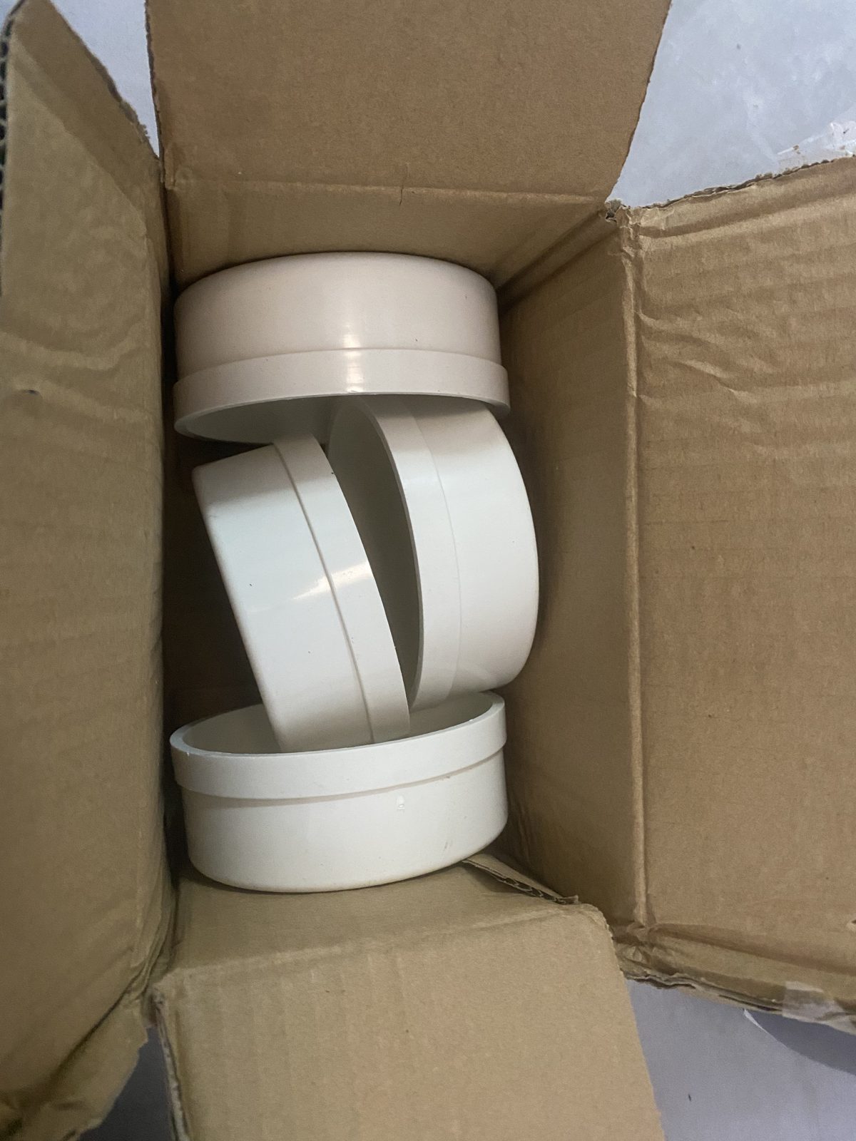
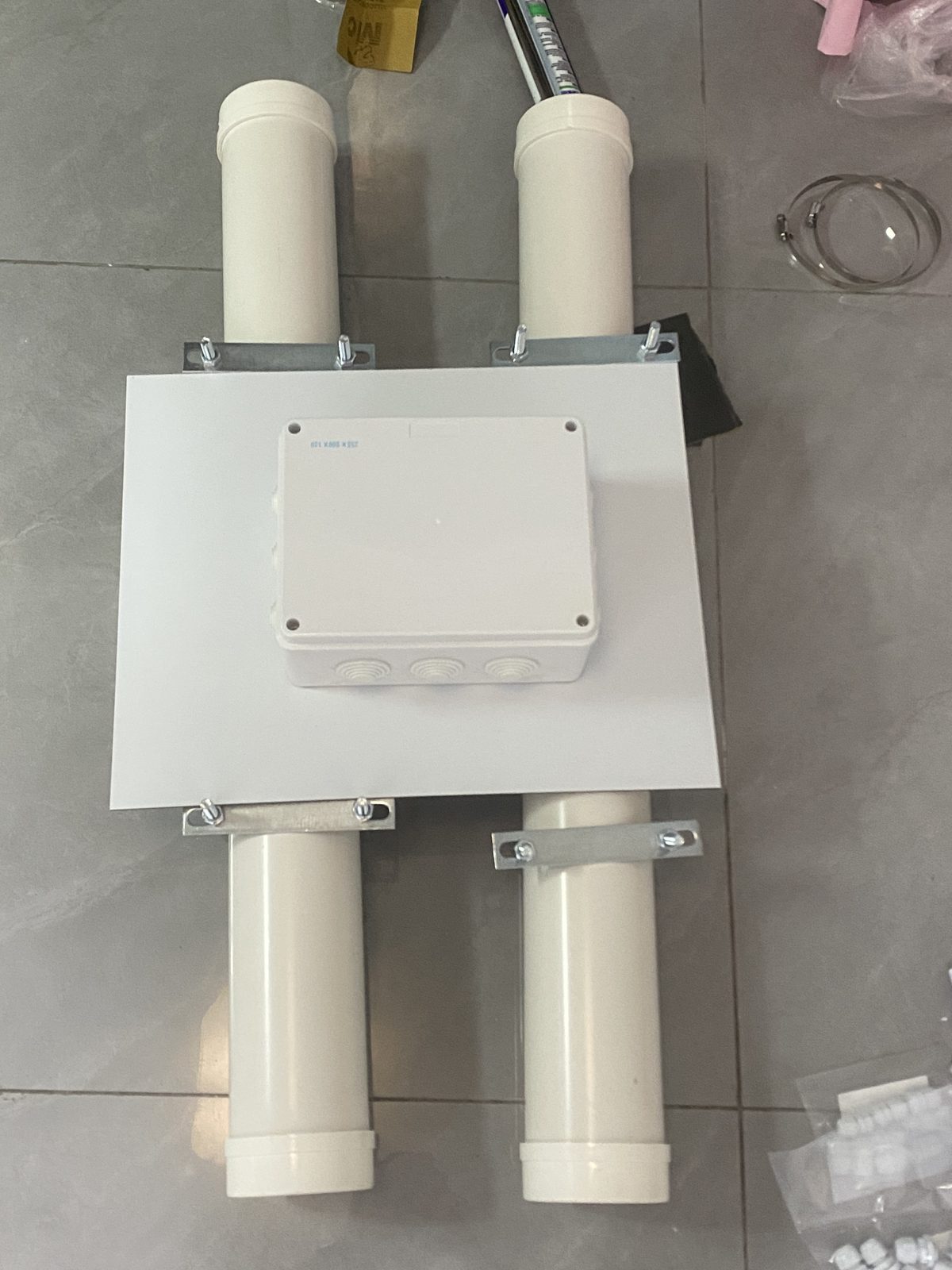
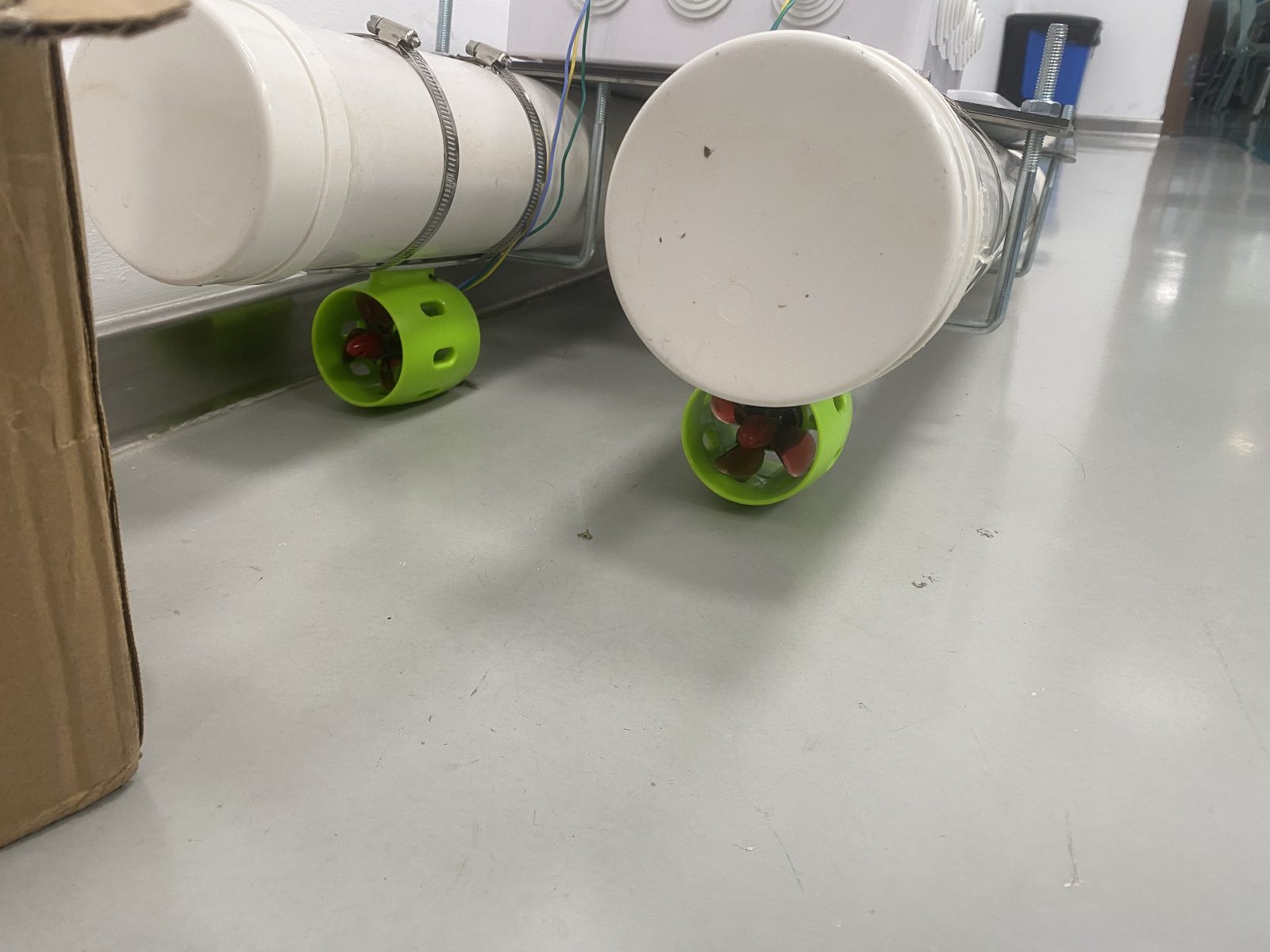
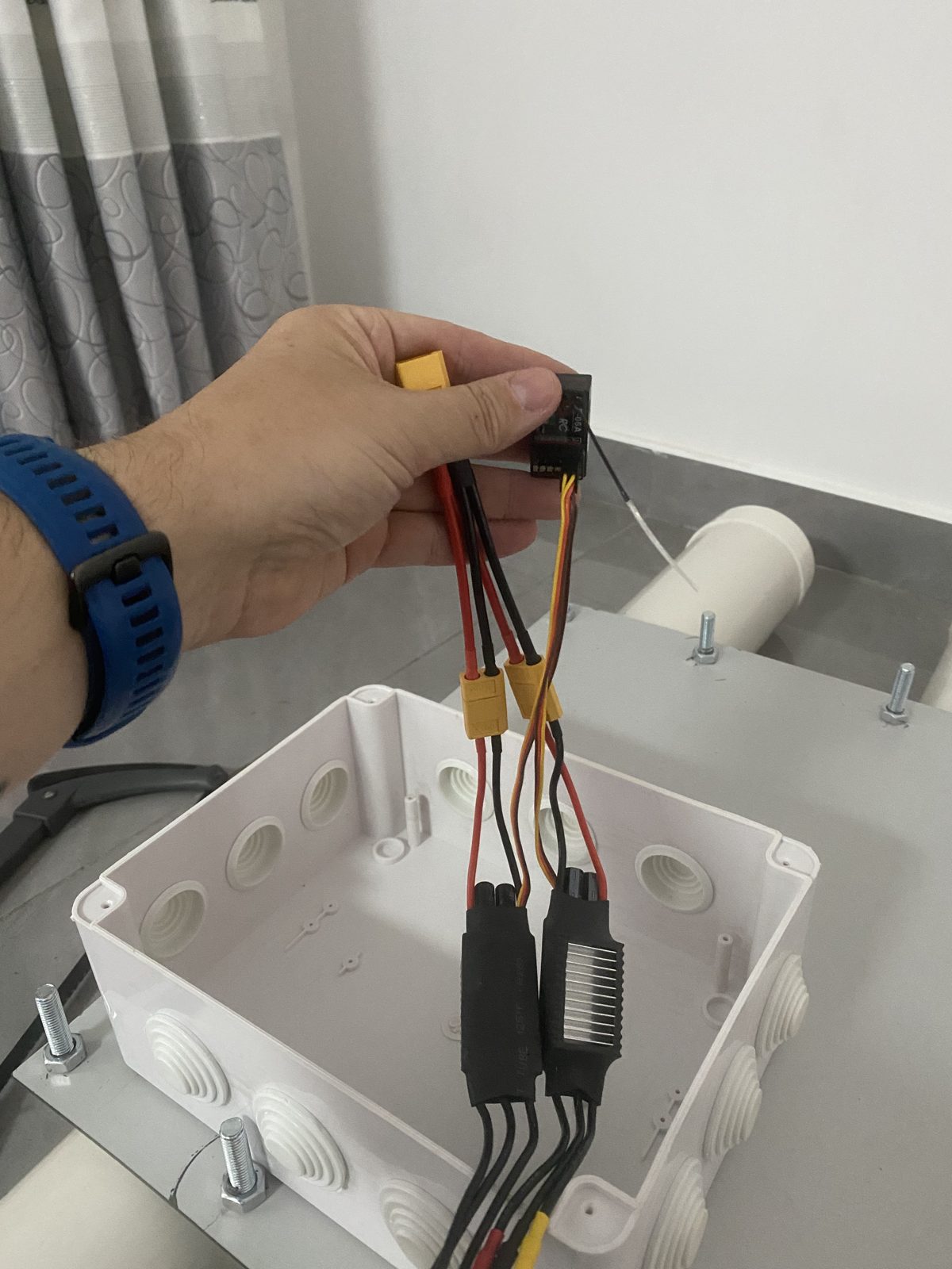
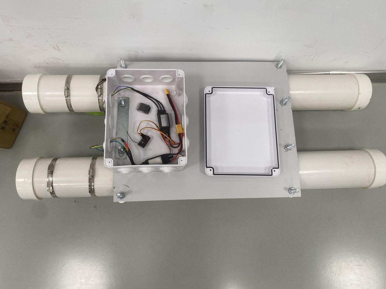
The hull is deliberately buildable with local hardware-store sourcing: PVC drain pipe, couplings, and end caps for the pontoons; a composite deck plate on threaded standoffs; stainless hose clamps for every mount. The hull uses readily available materials that students can assemble and modify.
Sea Trials
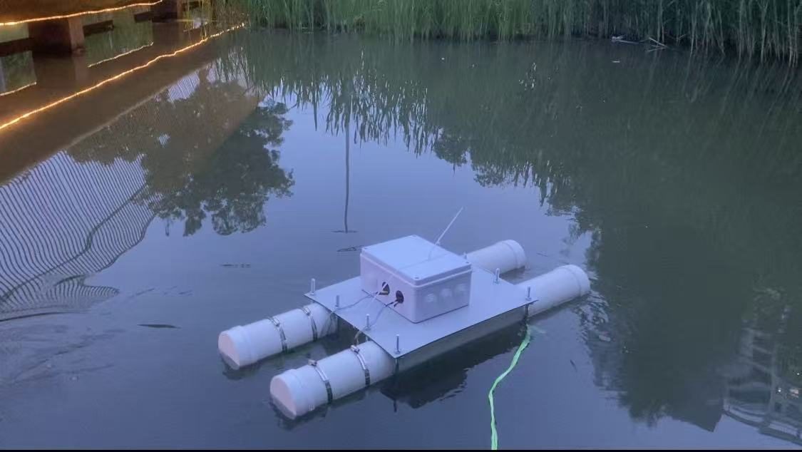
The vessel has been on the water. First float tests on a local canal checked buoyancy, trim, thruster response, and waterproofing with the vessel secured by a tether.
The Science Station
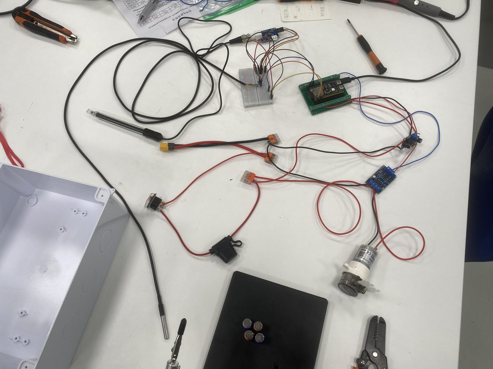
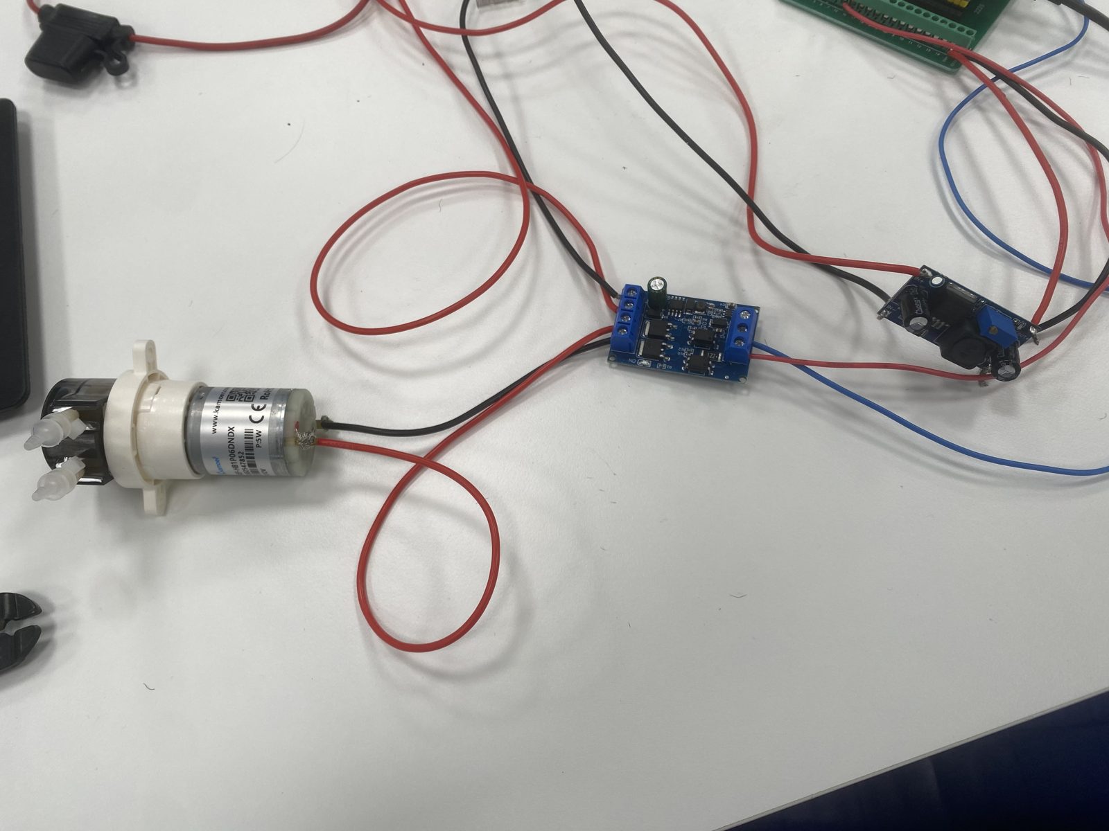
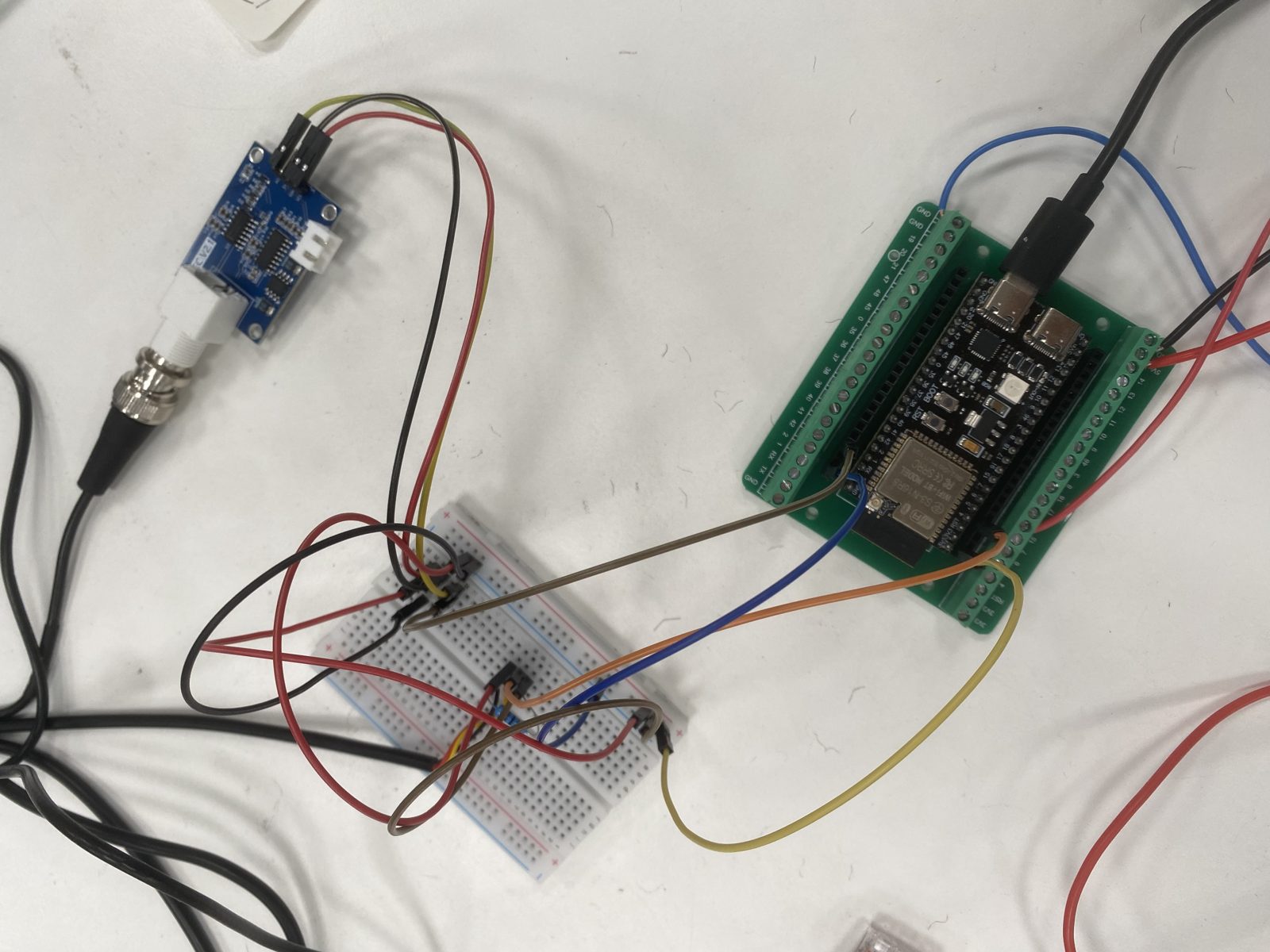
The working sensor-and-pump system that goes inside the vessel’s payload enclosure. A 12V battery feeds two branches: pump power switched by a MOSFET module under ESP32 control, and a buck-converted 5V supply for the ESP32 itself, which in turn provides 3.3V to the temperature and conductivity sensors. Click any component or net in the schematic to trace the wiring.
Click any component or net to trace the wiring. Two branches leave the battery: 12V through the MOSFET to the pump, and 12V through the buck converter down to 5V for the ESP32, which provides 3.3V to the sensors. The turbidity sensor is omitted — that board burned out during testing and a replacement is planned.
An earlier turbidity sensor board burned out during bench testing and is deliberately absent from the current wiring — a useful lesson in fault isolation that students documented before planning its replacement.
Bench Log
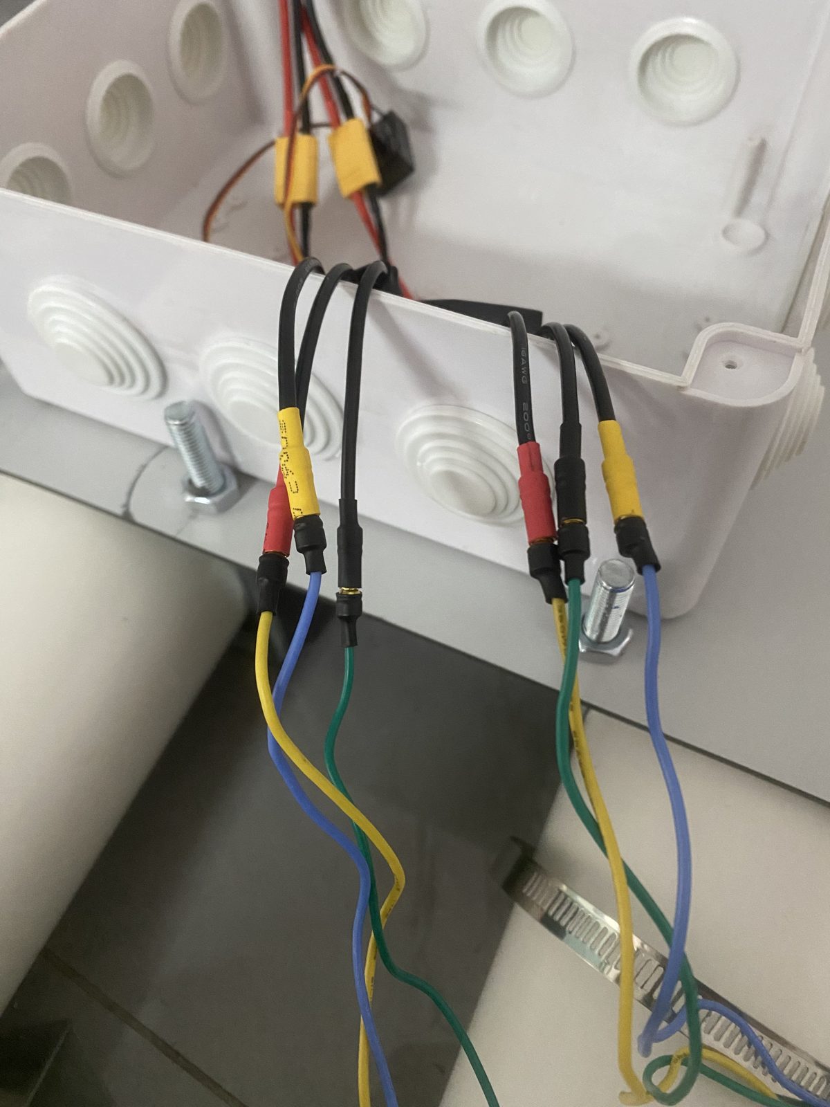
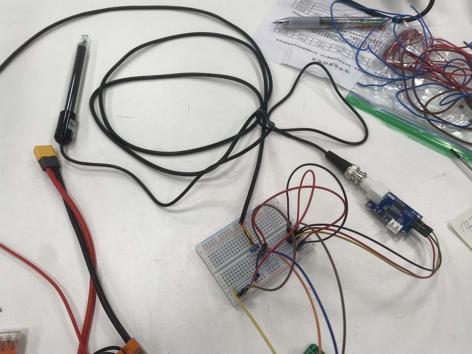
These photos document bench testing of the science station shown in the schematic, before installation in the vessel’s sealed enclosure.
Student Task
Design, build, test, and document a small monitoring vessel that can collect environmental readings from a local waterway. Students must justify their design decisions, present test data, and revise the prototype after field trials.
Assessment Method
Assessment combines engineering notebook evidence, working prototype performance, code quality, data interpretation, and a final technical explanation. A successful submission does not need to be perfect; it must show disciplined testing and intelligent revision.
Reflection
This project is strongest when students encounter real constraints early. Waterproofing, unstable readings and mechanical balance give students specific problems to investigate, test and resolve.